


Last week was the 77th anniversary of the famous “Dambusters” raid on German dams in the Ruhr valley. There are many sources of stories online describing Barnes Wallis’ innovative ‘bouncing bombs’, and the bravery of Wing Commander Guy Gibson and his 617 squadron crew. However, I wanted to shine the spotlight (pun intended) on the unnamed ground crew who had to prepare the Lancaster bombers for these crucial missions.
As you might know, in order for Wallis’ bombs to ‘bounce’ properly on the surface of the dam waters, they had to be dropped precisely from an altitude of 60 feet above the smooth body of liquid.
Early attempts used a low level altimeter from EMI, but that proved to be unreliable and not accurate enough for the purpose.
Legend has it that Guy Gibson himself (or one of his crew) had a brainwave to use two beams of light to triangulate the altitude of the bomber above the water. If you watch the famous black and white movie from the 50’s, it shows an aircrew member being inspired by going to a West End show and observing the two spotlights on either side of the stage focusing on the performer.
However research shows us that it was Benjamin Lockspeiser, the Deputy Director of Scientific Research at the Ministry of Aircraft Production who designed the actual light fitting for the bombers. Unlike Wallis and Gibson, his name is a little more shrouded in the history books, as most of the ‘boffins’ working in the labs often were. Here are his plans for the lighting system installation on the Lancasters:

Image courtesy of RAF Museum
The idea was that there would be two Aldis lights mounted on the nose and midships under the bomber. They would both shine a narrow beam spotlight downwards and off to the right of the aircraft. The two beams would meet at an exact point 60 feet below (and to the side of) the aircraft.
The navigator of the bomber, could look out of his blister window on the starboard (right hand) side of the aircraft towards the surface of the water in order to ascertain height. From this, he would simply convey the verbal instructions “Down, down, down” to the pilot until the beams met at a single point of light. The pilot then had to maintain a steady 232 knots and hold the aircraft level until the bomb aimer released the rotating drum bomb (and that method of judging the release point is another exercise in clever triangulation that I might discuss in another post).
Using my dimly remembered high school trigonometry to work out some details, I tried the following calculations.
The two beams were shone down from points underneath the bomber, and from the rough sketch above, it looks like the light under nose (X) was shone down at a right angle with respect to the airframe. The second light (Y) was mounted just ahead of the bomb bay about a third of the way along the aircraft and was angled to meet the forward beam at a distance of 60 feet. Because a Lancaster is just over 100 feet long, my estimations were that these two light were approximately 25 feet apart.
This gives us some starting points for a right angled triangle. We know the distance between X and Y is 25 feet, we know that the distance from X to Z, which is the point on the water surface is 60 feet, and that X is a right angle, so we have enough information to work out the angle α at Y.
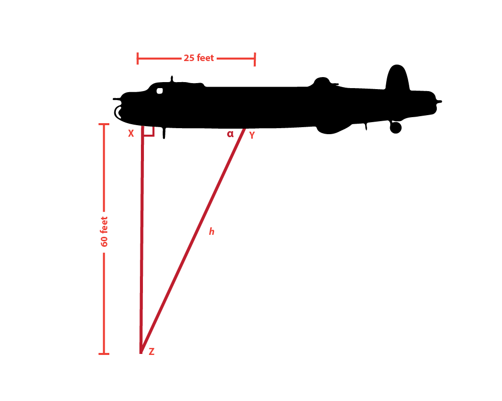
Well - nearly enough. We need to find out the length of the hypotenuse of the triangle. The distance from the light at Y to the surface of the water at Z. Let’s call this length h. Using simple trig given X-Y (25 feet) and X-Z (60 feet):

This gives us a result of 65 feet for the beam length from Y to Z. And from this, we can use an arcsign function to find the angle α of the light at Y:

This gives us an angle of 67.38° that the light needs to be mounted at in relation to the body of the aircraft
But wait! We have said that the lights had to be canted sideways as well, to enable the navigator to see them on the surface of the water. From pictures (and illustrations) I’ve seen, it looks like the beams meet in line with the inboard engine on the starboard side. A rough approximation from Avro Lancaster schematics shows me that this is approximately 15 feet from the fuselage centreline.
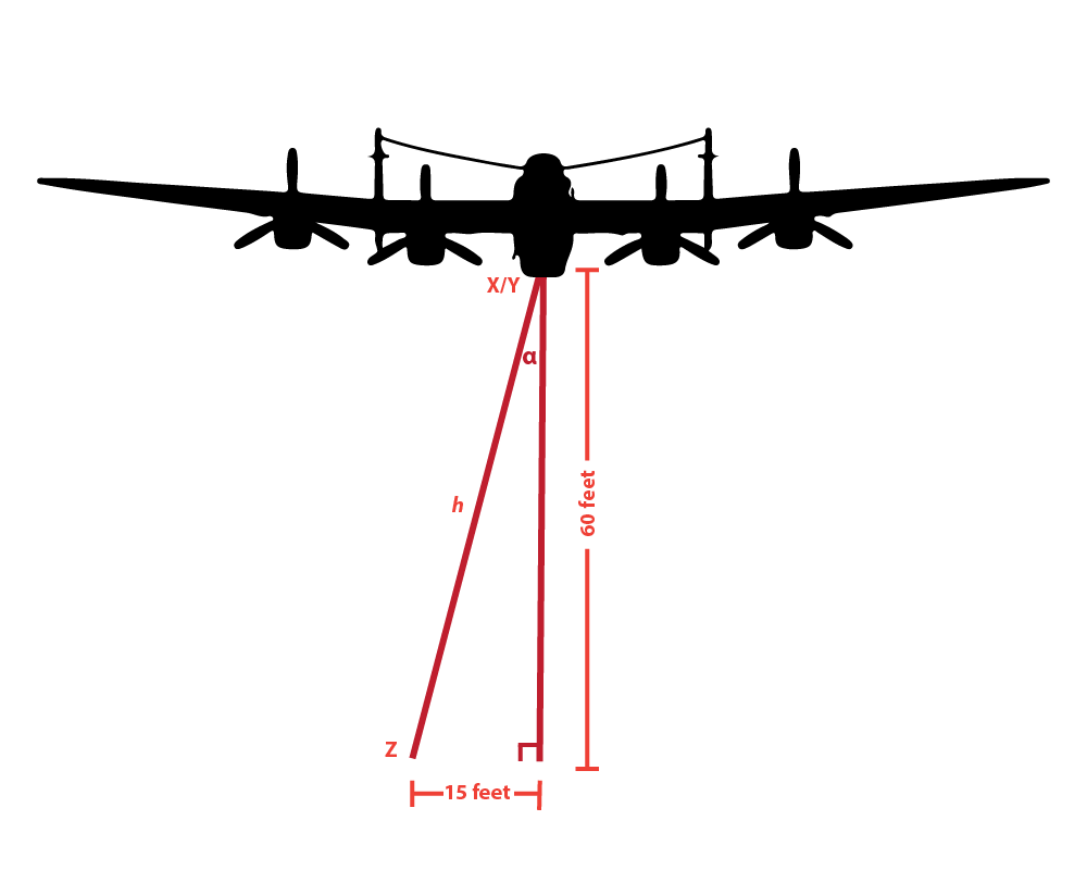
Hence the actual distance from X to Z is slightly longer than 60 feet, and we need to find the new distance to the surface of the water based on this offset.
Based on the same formulas above, I get that the new distance to the water h will be:

which gives me 61.85 feet beam length to the water. Both of these lights will also have to be canted 14.04° from the centreline of the aircraft.
So plugging all that back into the top two equations, we get:
Which gives us a rear light angle of almost exactly 68° - that is more than 1.5 degrees difference from our original, based purely on canting the light towards the side a little.
And here is the thing - for every 1 degree that the light is out, this will translate to a nearly 3 feet of difference in the convergence point. For instance, if the rear light was inadvertently set at 70°, then the beams would converge at 68.7 feet - more that the height of even the tallest crewman (in terms of difference from the required 60 feet).
For this reason, the mounting and calibrating of these lights have to be absolutely precise. They would have to be mounted at a set 90 degrees and 68 degrees, PLUS both be angled sideways at 14 degrees. If the sideways angling was not the same, then the two beams would not meet at all!

Sir Benjamin Lockspeiser
All this on a pair of lights on flimsy metal brackets, exposed to the whipping slipstream and turbulence and the jolts of heavy landings and incoming enemy fire.
I could not find any photos of the mounting brackets or adjusting mechanism for these lights, but it is all hats off to those anonymous ground crewmen who spent possibly many back breaking hours ensuring that the light were set perfectly before each mission. If not for these forgotten guys, Wallis’ bouncing bombs would have either sailed well over the dam walls, or not travelled enough length to reach them.
Finally, all credit to Sir Ben Lockspeiser (1891-1990), for inventing the lighting altimeter system, and who later went on to become the first President of CERN, which is home to the Large Hadron Collider today, and continues to push the bounds of human research.